Showing posts with label Tools. Show all posts

Sunday, December 16, 2018

Shop Made Carbide Tool

Can a Carbide Tool be Made in the Shop?

The short answer is yes! 

Materials:
  1. A piece of 1/2" square stock (I got mine from McMaster). I do not recommend using carbon steel. Something like this should be adequate. 
  2. A cutter blade and tapered screw. Many are available choose one that fits the size stock you are using. They run from $9 to $20. 
  3. Handle shop made or universal handle.
  4. Total cost less the handle could be <$20.
Tools:
  • Grinder
  • Hand file
  • Drill and Tap for the carbide cutters screw
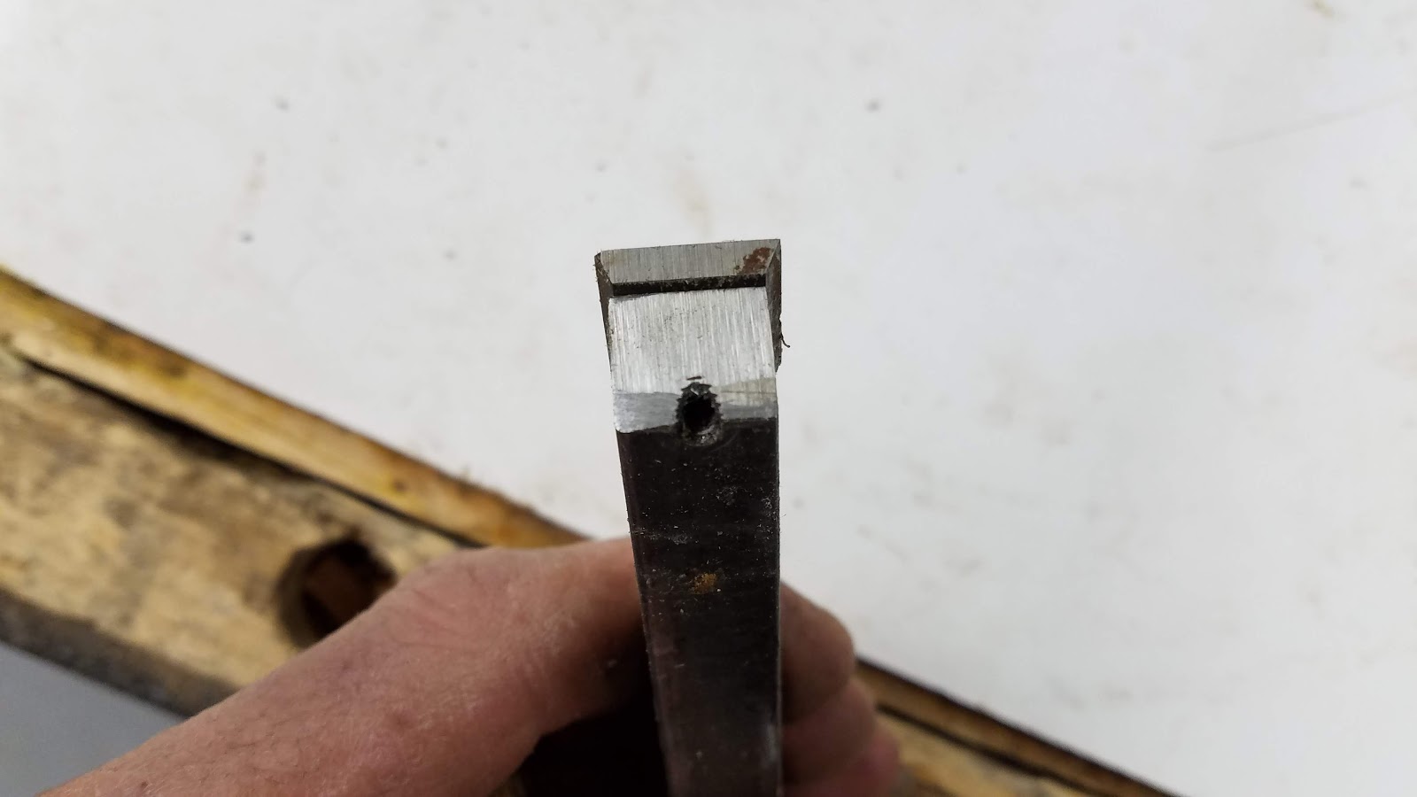
The biggest challenge with making this tool is getting the position of the tapped hole in the right place. It needs to be placed exactly between the end of the stock and the rear of the perch. 
The second challenge is to get the grind on the back of the porch for the cutter in the right place at the right angle so the stock does not dull the cutter but also holds is straight.
After doing this the hard way I would recommend this approach:
  1. Lay the cutter on the stock leaving about an 1/8 inch of material protruding beyond the front of the cutter.
  2. Mark the front and back of the cutter laying on the stock 
  3. On the side of the stock mark the depth that the cutter needs to be recessed 
  4. Grind the perch down to the recessed depth on a grinder. Do not grind beyond the mark where the rear of the cutter will sit. I ground a bit in front of it.
  5. Using a file dress up the perch so that it is flat and parallel to the stocks bottom surface.
  6. File an angle on the back of the perch that matches the cutters angle. I used 45 degrees.
  7. Lay the cutter back on the stock fully engaged with the rear of the perch and mark the hole
  8. Accurately drill and tap a hole for the the retaining screw. You may need to drill a small recess in the top of the hole because the bottom of the tapir in the retaining screw may not have threads. This relief will allow the screw to fully seat in the cutters tapir and grip tightly.
  9. Mark and grind the front nose of the stock to match the angle on the front of the mounted cutter.
  10. Insert into a handle or make a dedicated handle for the tool.
Square cutter sitting on perch

The front angle was ground first and ended up a bit short :)
See the process above to prevent this. This error may make this tool grabby!


Inserted into handle

Note: you should be able to mount a round carbide on this tool but of course a diamond shape will not fit. I would expect that the rear of the perch can be relived with a dremel tool to accept a diamond cutter.

Enjoy and comment,
Don


Storing Tool Rests on the Stubby

Organizing Tool-rests

I found myself walking across the shop all the time to change tool rests. I decided to locate them on the lathe.
You can also see the tail stock hinge I have been using for years to avoid lifting that thing to the floor and back.


Enjoy and comment,
Don

The Stubby Gets a Control Panel Post

Adding a fixed place for the Stubby's Pendant

I am always looking for ways to make my turning process more efficient. This week I realized that I spend a lot of time moving the pendant around the bed. I like this flexibility but at the same time really just need it within reach. I came up with this solution.
The post is attached to the short bed with a cartridge bolt whose head is ground down to fit the large hole in the key way. This way I can change the position of the post or remove it easily by loosening the wingnut and sliding the post downward and out.

Positioned if your turning on the left side and its in the way

Typical position of the post

Attachment detail

Carriage bolt ground to fit into the key way

This is what was added...
Enjoy and comment please;
Don

Sunday, December 9, 2018

Saw Blades Storage Box

A Simple Way to Store Lots of Saw Blades

I decided that my table saw blades needed a home other than being stacked in a corner potentially chipping the teeth. I canvased the web looking for ideas for a storage container. I found lots of great ideas but they all required building containers for each blade. A nice idea but I didn't feel like investing that amount of time and wood.
So while looking around my shop for inspiration an empty crate "spoke to me" and the project started.

This blade holder is compact, inexpensive and protects all the teeth of all the blades. The blades do not touch each other and the blades never touch anything but wood and plastic.
It is easy to store and carry using the crate handles.
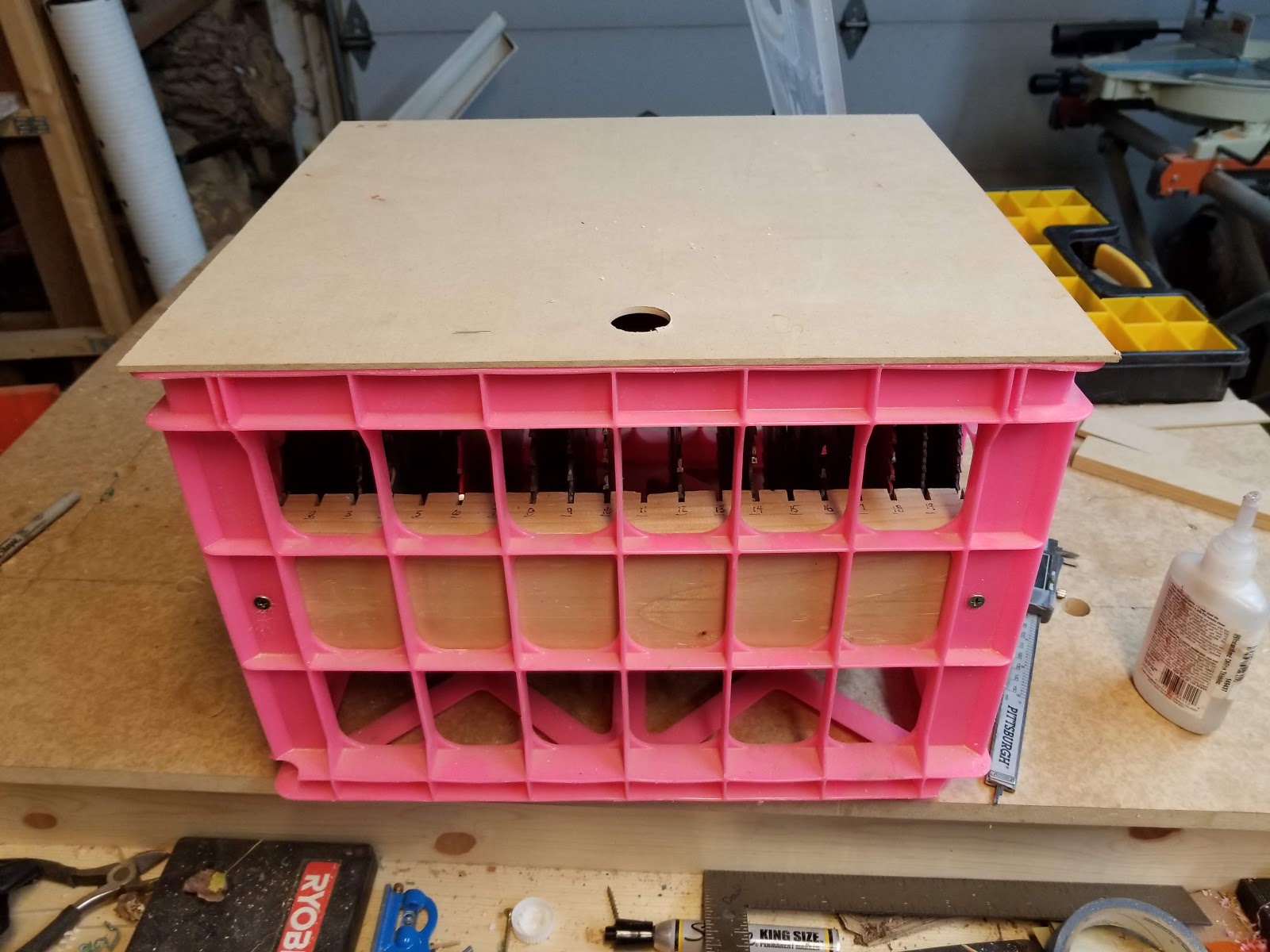
This crate stores 20 blades

Design

The idea was to stack the blades on edge pinned between 2x 2x4's that were screwed to the side of the crate in the center of its depth. That seemed simple enough.
Any crate will work, mine was a 12" wide file crate. Pink is not my first choice but it was sitting on the floor staring at me. 

Fabrication

Fabrication was simple, just cut 1/8 slots crosswise in each 2x4. Its nice that the blade on any saw is the exact kerf of the blade that will go in that slot...Hello! Although I have some thin kerf blades the widest kerf blade was used to make the cuts.
I knew however that if the slots in each of the side inserts did not align across from each other perfectly the blades would probably bind going in. With a 1/8" slot there is not a lot of room for cumulative errors.

Prepare the Slotted Inserts

Step 1: cut the 2 x 4's to length so they fit perpendicular to the long inside dimension of the crate. A snug fit is important so that the slots in either side will line up.

Step 2: plane and joint the 2 x 4's flat and square. [you could skip this step if you had reasonably straight and flat dimensional lumber]

Step 3: with CA and accelerator glue the 2 x 4 edge to edge so that they act like one board. This will insure that the slots on each insert will be cut in exactly the same place. Just use a few dots of super glue. We don't want a permanent bond just enough to keep them registered.

Step 4: calculate the depth of the slot based on your final dimensions of the Slotted Inserts. 

Slot Depth = (ID-(2*SI))/2

Where:
     ID= Inner dimension of the crate. The dimension parallel to the direction the blades will be inserted.
     SI= final thickness of Slotted Inserts

Cut the Slots

Step 1: Set the Slot Depth. I used the depth stop on my miter saw.
Step 2 : I used two aids to mark and cut the slots. 
  1. A 1/8 thick piece of MDF to wedge in the slot after cutting. 
  2. A  1/2 thick piece of MDF to use as a spacing gauge. [Made from 2x pieces of 1/4 thick MDF CA'd together] 
Depth stop swung into place on miter saw

1/8" MDF wedge keeps boards aligned and provides a reference for the next slot.
These Slotted Insert boards are temporarily glued together.

1/2' spacing gauge up against the wedge to mark next line

Aligning the slot and cutting it on miter saw
Step 3: Follow this process for cutting the slots:
  • Mark and cut the first slot 1/2" from one edge of the Slotted Insert glue-up then
    1. Insert the wedge in the last cut slot
    2. Hold the spacer gauge against the wedge and mark the next slot cut line
    3. With the wedge still installed in the last cut use the laser guide to set up and cut the next slot
    4. Go to sub-step 1 and repeat until all slots are cut. I cut 20 slots.
  • Mark the same ends of the Slotted Insert sections so that when you part them you will know which end points the same direction
  • Break the two Slotted Inserts apart. I just rapped the joint on the edge of the bench and the super glue gave way.
  • Number the slots on the top edge, this aids in lining up either side of the blade when inserting into the crate.
Breaking the two Inserts apart

Mounting the Slotted Inserts and Loading Blades

Screw the inserts 1/2 say down inside both sides. Drill pilot holes and screw from the outside.
Load in your blades. Some organization is useful. I loaded mine from the right to left. Highest # of teeth on the right moving to the lowest on the left. Hmm that feels backward!

Add a Top for Safety

I advise making a top to protect the tops of the blades and any of your body parts that may come in contact with the sharp teeth.

Top shown upside down.
Note the Slotted Inserts mounting screws 1/2 way down the face of the crate

Completed Blade Storage Box
Like any sharp tool in your shop the cutting edges can ..... well cut. You need to use care when handling saw blades and grab the blade from the crate with a pair of gloves. You will notice some bloody decorations on the top of my box. Yep cut myself!
Nicely tucked away in a corner
Enjoy and comment;
Don


Friday, December 7, 2018

Universal Table Saw & Router Depth Gauge

Why a Different Depth Gauge

Do you have a number of those cheap digital micrometers around the shop. I do in fact I have one in each major station of my shop; table saw, router, main bench, lathe and drill press.

A popular hack is to use these same micrometers as a shop made depth gauge.
This article inspired me to make a version of my own.
I wanted the same gauge to be able to set depth and also to accurately set the fence relative to the cutting blade .... measuring from either side of the blade.

Setting the fence is easy if you have an accurate glide on the fence and you are measuring from the fence side of the blade. However when you need to measure the distance to the fence including the kerf of the blade the process can be less accurate. Sure you can do the math to account for the blade kerf but sometimes the blade is not exactly the width you might think and if you change blades a lot you have to remember what exact kerf goes with what blade. Yes, I am talking about getting close to 1/32 accuracy.

The design

An L shaped frame is fabricated from MDF to firmly hold the mic (micrometer). This design captures the mic at the top of the frame and at the bottom of its sliding arm providing a large depth measuring ability. For me this is the highest position my table saw can achieve.

The L shaped frame is made so that it can lay flat on the table of the saw for accurate fence positioning.

The mic is held in place by a miter miter cut in the frame and by a second holding piece that sandwiches the mic between itself and the frame.

You will have to cut the miter to fit your particular mic as they all have different means of securing the spline (the moving rod) at the end of the slide. Cut the miter depth just short of the thickness of the mic's slide so the holding piece can grip the mic's slide when the wing screw is tightened. Make the miter to shallow to start and the pare away with a chisel until the slide and the holding piece have an interference fit.

The holder is fastened to the first frame by a wing screw (1/4-20 in my case) which is screwed into a pronged Tnut that is inserted into the opposite side of the first frame. The Tnut is countersunk so that the frame will lay flat on the table. I had to grind the wing screw flush with the Tnut so the tool would lay flat.


Frame [3/4 MDF]


Back side


Miter in top right of frame

Measurement

This tool can measure blade height or fence position accurately.

Blade Height Measurement

The height of the blade can be measure easily:

TURN OFF THE SAW!
  1. Position the tool on the table with the foot of the frame flat on the table. Make sure your blade insert plate is flush to the table and not biasing the tool.
  2. Move the mic's body until the spline touches the table, zero the gauge.
  3. Move the gauge to the value that matches the depth * you want the blade to cut. 
  4. Position the tool next to and perpendicular to the blade.
  5. Move the blade up to touch the spline
*Note: the gauge will read negative values. Ignore the - sign


Fence Position Measurement

Setting and measuring the distance from the blade to the fence is easy;

TURN OFF THE SAW!
  1. Lay the tool face up on the surface of the table an perpendicular to the blade
  2. Push the foot of the tool up against the fence
  3. Move the gauges body until the spline touches the fence
  4. Zero the mic.
  5. Move the body of the gauge until it reads the distance* you want the fence from the blade, lock the gauges body
  6. Move the tool up to and perpendicular to the blade with the spline touching the side of the blade you want to make the cut from.
  7. Hold the tool firmly down on the table and move the fence over until it touches the foot of the tools frame [adding a magnet on the back side of the frame may be a good improvement]
  8. Lock the fence and check the position again by holding the foot against the fence and observing the position of the spline in reference to the blades teeth.

Zero the mic

Set the desired cut width

Position the spline on either side of blade and move the fence over to touch the foot of the tool.
Enjoy and comment,
Don


Sunday, November 4, 2018

Thin Strip Cutter

Cutting Thin Strips Simply & Safely

Its not uncommon to need thin strips of wood and plastic materials for embellishments to various projects.
This is my version of a thin strip cutting jig that focuses on safety and simplicity.
This jig takes between 30 minutes to 1 hr to complete.

This jig will cut 1/16 thick materials without getting caught below the jigs stop block. Shown in the photo is a 1/16 x 1/16 strip cut from fiberboard.

Parts of the Jig

The jig consists of a MDF base, a sliding arm, a retaining knob, a miter slot guide and a bearing assembly. 
I have not included a drawing or dimensions as yours may be different based on your type of saw and what scrap you have available.
You need base material to be thick enough to accept a dado and still be stable. I used a 3/4" piece of scrap MDF.

Base


The base is a scrap of MDF about 6" wide and 3/4" thick with a dado slot that is cut on its top surface 90 degrees to the table.
The bottom of the base has a miter slot guide screwed/glued to its underside that runs the length of the base and parallel to the blade. Its important that this guide be perpendicular to the blade when the guide is in the miter track of your saw.
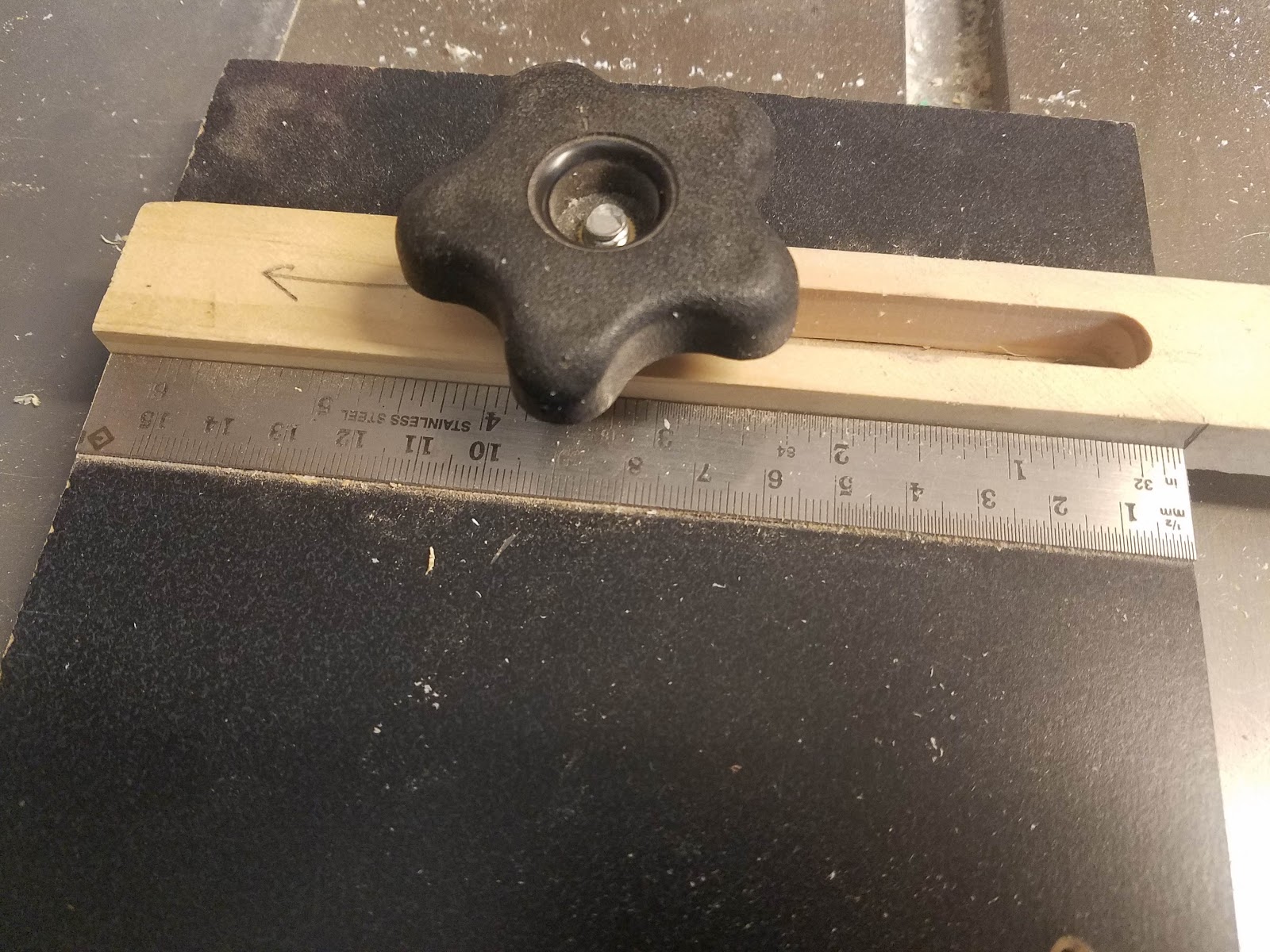
Optionally you can glue a ruler to the base near the sliding arm so that the gap from the bearing to the blade can be set or observed. The gap is the thickness of the strip being cut.
There is a 1/4" bolt hole drilled in the center of both the dado slot and the width of the base. The bolt in stalled in this hole accepts a 1/4" knob which serves to lock the sliding arm in place.

Sliding arm


The sliding arm is a piece of scrap whose width is cut to fit the width of the dado and long enough to reach the saw blade when its it deployed. 
The sliding arm has a slot routed long enough to reach the blade when installed in the miter slot of the saw.

Bearing Assembly

One end of the sliding arm has a 1/4" hole drilled as close a practical to its end and in the center of the arm.
In that 1/4" hole a bearing is mounted using a, washer and wing nut. 
The sliding arm is sanded in an arc as to give the bearing as much exposure as possible.
Any bearing will work as long as it fits between the sliding arm and surface of the saw. You may also need to adjust the placement of the hole in the end of the sliding arm accordingly. 
The head of the 1/4-20 bolt was ground to its minimum thickness in order to keep the bearing as close to the tables surface as possible.
There is a plastic washer on either side of the sliding arm to keep the bearing from binding when the wing nut is tightened.
On the bearing, check that the shoulder on the bore for the shaft is proud of the bearings sides so that when a surface is pulled tight against the bearing it will not bind against the bearings race.
This bearing [from my stash] has a retaining boss (see bottom ridge) that nicely reduces the area that the wood being cut sees, reducing error and friction.

Using the Jig

Using the jig is simple. Insure that you use a zero clearance blade. It will keep the thin strip from falling into down the side of the blade and also minimize tear out.

Slide the jig forward in the miter slot so that it is positioned directly across and perpendicular to the starting teeth of the blade.
Release the knob and deploy the sliding arm until the bearing contacts (tangent to) the side of the blades teeth.

Move the sliding arm away from the blade equal to the desired width of the cut strip.
Tighten the knob on the sliding arm.

Adjusting the fence to hold the wood against the bearing. Note the wood is not touching the blade!

  • Pull the base back toward the front of the saw well away from the blade.
  • Insert a piece of wood against the bearing and bring the fence over to touch its opposite side.
  • Adjust the fence such that the wood is captured between the fence and the bearing.
  • Now your fence is set such that a thin strip will be cut from the side of the wood opposite the fence.  
  • **Start the saw with the wood pulled back from the blade
  • Using a push stick, push the wood through the blade-fence slot cutting off a thin slice.
  • After turning off the saw and waiting for the blade to stop, make subsequent cuts by pulling the wood backward until its clear of the blade. 
  • Release the fence and move it and the wood toward the bearing until the side opposite the fence touches the bearing. 
  • Lock the fence and go to step **....
Safety note: to avoid a kickback do not pull wood backward through the blade while it is running.

Improvements

Lock the Jig

The jig's position could be locked into the miter track by drilling a hole through the base and miter guide. A flat head tapered shoulder screw is inserted in that hole from the bottom. When a knob on that screw is tightened the head of the tapered screw will cause the wood to swell in the track and lock it.

Note: I have never seen the need to lock the jig in place as there is little friction between the bearing when rotating and the wood being cut. Even if the jig moves forward and back that does not create an error in the cut.

Example locking technique and gcode: https://www.youtube.com/watch?v=G3-3x9qNXws

Or you can buy these clamping tracks: https://www.rockler.com/miter-slot-hardware-kit

Other Jigs and Approaches

WoodWorkWeb (I do not like the potential to kickback with this approach).

Shop Notes

Woodsmith


Enjoy and comment,

Don